Simple Lane Line Following with Camera on F1Tenth Car
Introduction
This post is about using the Logitech monocular RGB camera to make simple lane line following and tested on the physical F1tenth car.
Lane Line Following
- step 1: Install and run ROS image node using the Logitech monocular RGB web camera
- step 2: Make camera calibration of monocular camera
- step 3: run image_proc node to publish calibrated color image
- step 4: Make edge detection of the streaming images using OpenCV library
- step 5: Set and tune the steering angle based on the edge detection result
Implementation Explanation
My implementation of the simple lane following using camera consists of these steps(each step corresponds to that in the above algorithm):
- step 1: Install and run ROS image driver node(in our case:cv_camera) and publish /image_raw and /camera_info topics from the Logitech monocular RGB camera
-
step 2: To make camera calibration, I used the checkboard which size is A4 - 25mm squares - 8x6 verticies, 9x7 squares. A good source for Calibration Checkerboard Collection
Then we can run ROS cameracalibration.py to calibrate the monocular camera. First there is a window pop up where you should move the checkerboard back and forward, up and down, skew and tilt. When the calibrate button is activated, this denotes that enough correspondences of corners have been found in order to solve the fitting problem to solve the intrinsic matrix of the camera. Then we can clicked calibrate, and then save, a .yaml file called camera.yaml will be generated under the folder of /.ros/camera_info
camera calibration interface
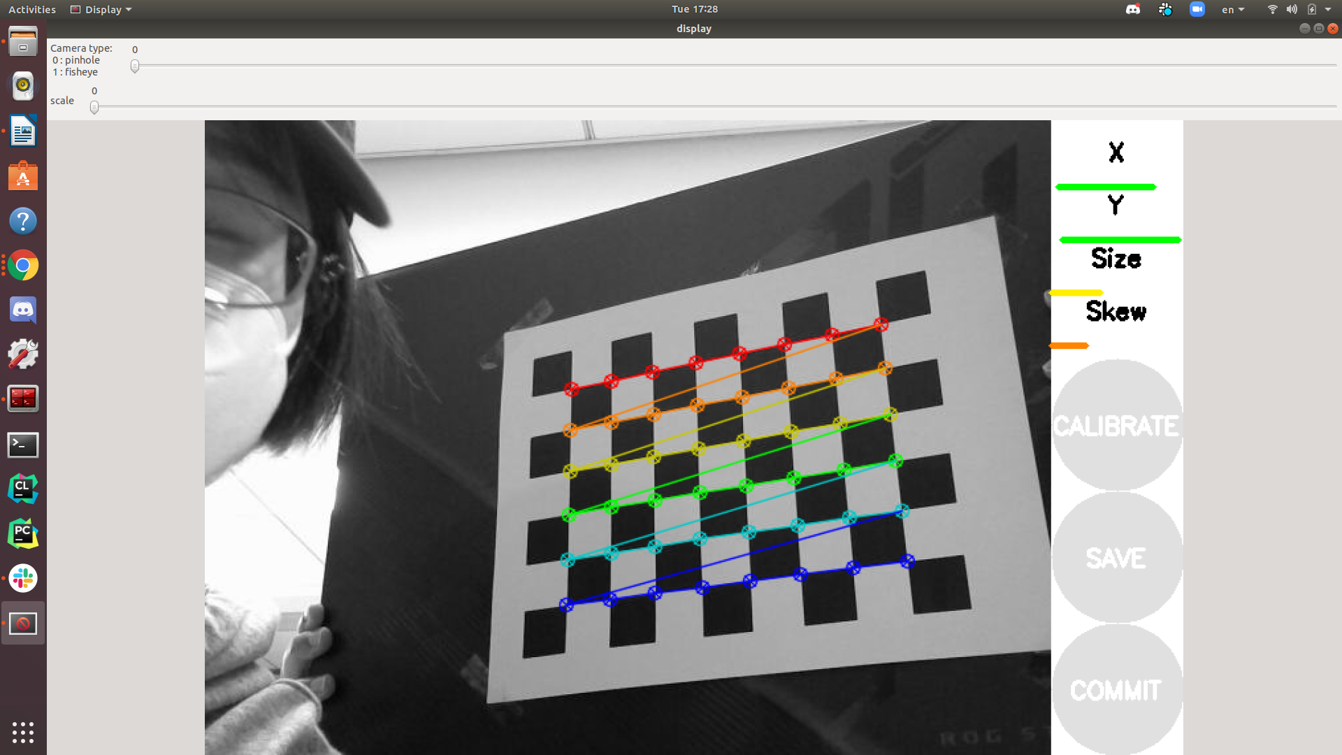
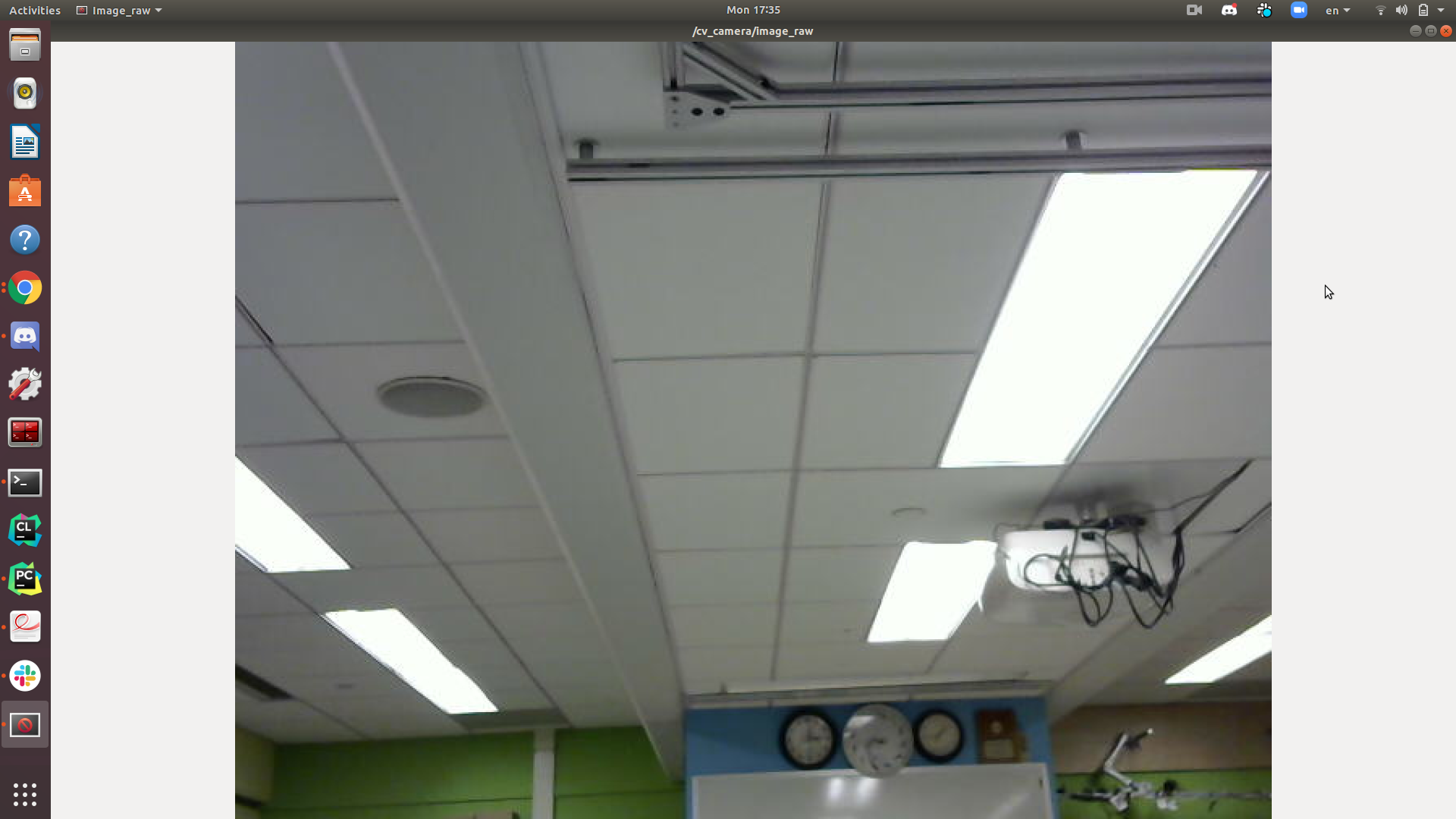
image from /image_raw topic(without camera calibration)
-
step 3: After we got valid camera.yaml file, we can automatically publish calibrated color image by running image_proc node
image from /image_rect_color topic(with camera calibration)
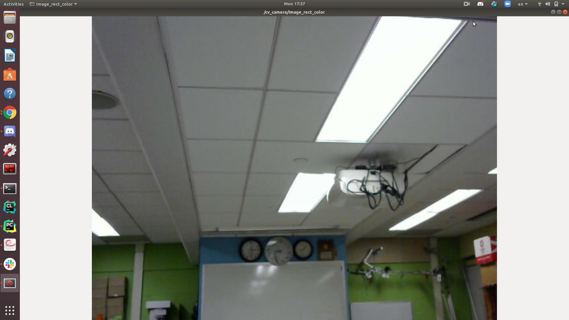
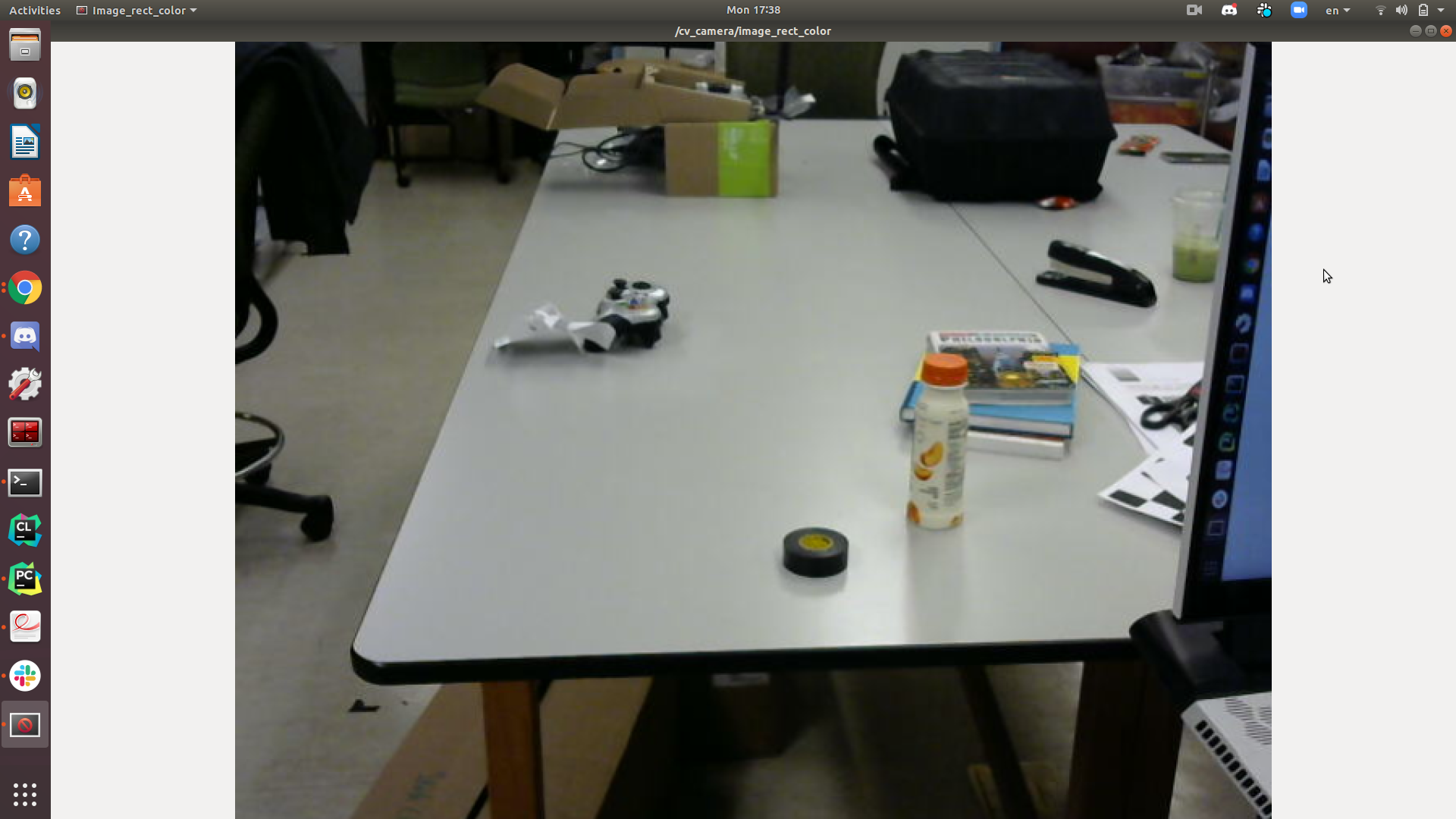
It seems that our monocular camera doesn’t have much distortion. After the camera calibration, we should see all parallel lines keep straight in the calibrated images.
-
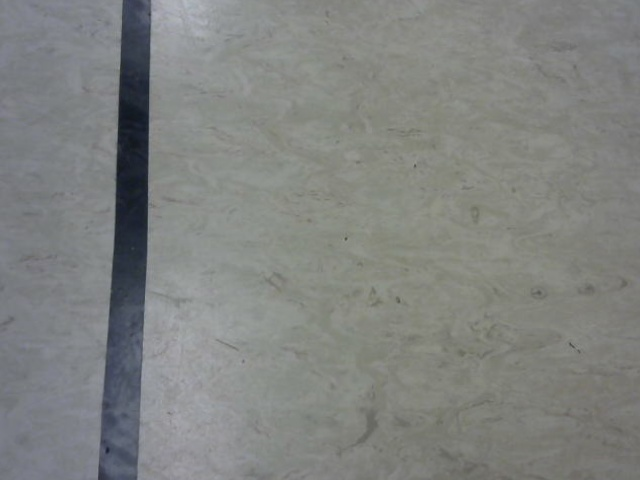
step 4: Our original image from the web camera is in the RGB color space. To make the lane line more distinguishable, I chose to conver the color space from RGB to HSV color space, then tune a lower and higher threshold of the HSV value and apply this condition to get a binary mask of the oirginal image.
Original calibrated color image
Mask using HSV color space
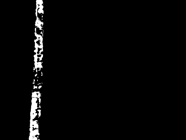
Then I traversed the 2D binary mask and sum the value of each column to get a 1D histogram. I choose the index of highest value and set it as the activated index to steer the car.
- step 5: Similar to calculating the cross track error, I calculated the absolute deviation of the activated index from the midpoint index of the image width. Since the width of the lane line is about 45 pixels in the image, I set several threshold for the car to decide whether to make turns and how much steering angle it should take accordingly. I published the final driving message using the ackermann_msgs/AckermannDriveStamped.msg