Wall Following
Introduction
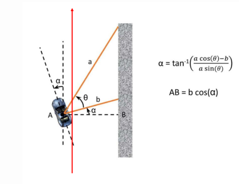
This lab is about the implementation of wall following algorithm to make the car drive autonomously following the left wall of the Levine Hall map. The idea is that by using two laser beams with given angles, we can calculate its distance from the wall, then obtain the Cross Track Error. By using PID controller, where the input is Cross Track Error and the output is the correction of steering angle.
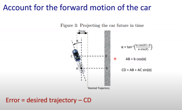
However, since our f1tenth racing car is in high speed, we need to take the forward distance into consideration. In the image below, the forward distance is denoted as AC. It is a user-defined value. The smaller AC is, the shorter distance you want the car to traverse to reach the desired track(where Cross Track Error is 0).
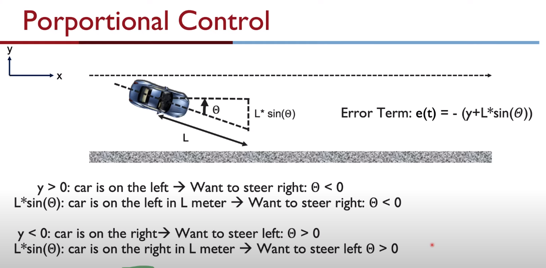
The sign relation between steering angle and the Cross Track Error is shown below. Note this is very important.
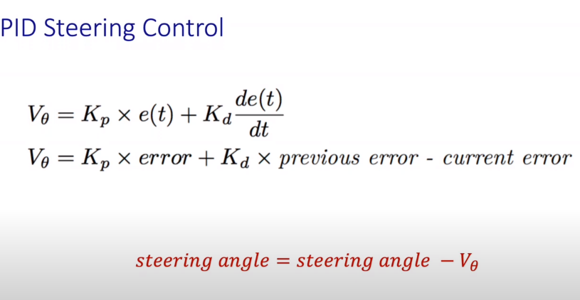
The general formula of PID control is as below.
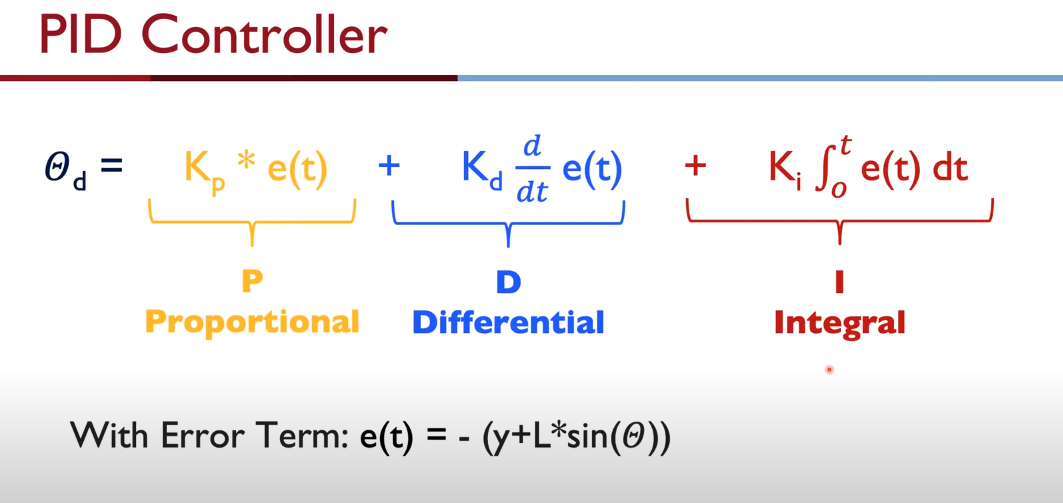
In my case, I found the PD controller is sufficient for this task. The PD steering controller is shown as follow.
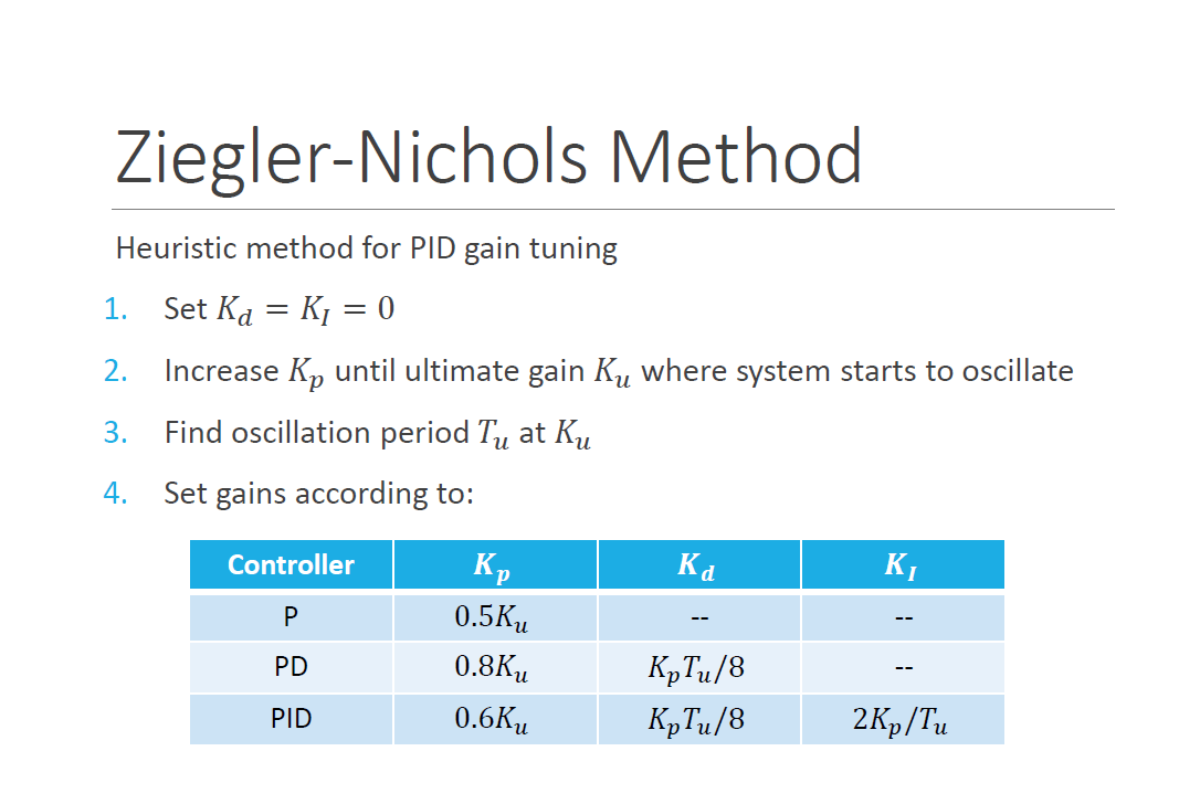
When tunning the parameters for a better performance of PID controller, it is a good practice to refer to Ziegler-Nichols Method.
Implementation Explanation
My implementation of the wall following node consists of these steps:
- step 1: Obtain two laser beam of LaserScan a and b, where b is normal to the x axis of the f1tenth car and in my case a is at 45 degrees from b towards front. Since we would like to make a left wall folloing, b should point towards left, which in terms of the LaserScan is +90 degree while a is +45 degree. Since our real f1tenth car uses the hardware Hokuyo 10LX, which has 270 degree scan field, therefore in simulation, LaserScan angle beyond [-135, 135] degree should not be used. In addition, we also need to make sure that the two beam scan we choose is valid by filtering out all Lidar beams with inf or nan value. If the two beams accidentally have invalid range value, we simply discard them, use the closest valid beam and adjust the theta accordingly.
- step 2: Use the distances a and b to calculate the angle alpha between the car’s x axis and the left wall and use alpha to find the current distance D_t to the car.
- step 3: Self-Define the length of L(also AC), then we can obtain D_t+1. Note that L is a key parameter to tune.
- step 4: Calcuate the Cross Track Error with lookahead distance considered, feed it into PID controller, the output is the correction of the steering angle. Notice the negative sign in front of the angle correction which aligns what we discussed about the sign relationship between steering angle and error.
My Demo
The wall following node is written with rospy.
Related Learning Resources
UV F1/10 course Video:
Upenn F1/10 course Video: